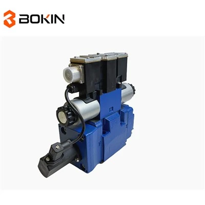
Designing an optimal control algorithm for electronically controlled hydraulic proportional valves is a complex yet rewarding endeavor. As a supplier of electronically controlled hydraulic proportional valves, I've witnessed firsthand the importance of a well - designed control algorithm in maximizing the performance of these valves. In this blog, I'll share some key insights on how to design such an algorithm.
Understanding the Basics of Electronically Controlled Hydraulic Proportional Valves
Before delving into the control algorithm design, it's essential to understand the fundamentals of electronically controlled hydraulic proportional valves. These valves are used to control the flow, pressure, or direction of hydraulic fluid in a system. They operate based on an electrical input signal, which is proportional to the desired output of the valve. For example, a higher electrical current may result in a larger flow rate of hydraulic fluid.
The Ng6 Proportional Valve is a popular choice in many hydraulic systems. It offers precise control over the flow of hydraulic fluid, making it suitable for a wide range of applications. Similarly, the Proportional Spool Valve and the Direct - Acting Hydraulic Proportional Valve 4WRPEH10 A1 10V Control are also widely used due to their reliability and performance.
Requirements for an Optimal Control Algorithm
An optimal control algorithm for electronically controlled hydraulic proportional valves should meet several requirements. Firstly, it should provide accurate control. The algorithm must be able to precisely adjust the valve's output based on the input signal, ensuring that the hydraulic system operates as intended. This requires a deep understanding of the valve's characteristics, such as its flow - pressure relationship and response time.
Secondly, the algorithm should be robust. Hydraulic systems often operate in harsh environments with varying loads, temperatures, and pressures. The control algorithm should be able to maintain stable performance under these changing conditions. It should be able to adapt to disturbances and uncertainties in the system without sacrificing control accuracy.
Another important requirement is efficiency. The algorithm should minimize energy consumption while achieving the desired control objectives. This is crucial for reducing operating costs and improving the overall sustainability of the hydraulic system.
Steps in Designing the Control Algorithm
1. System Modeling
The first step in designing a control algorithm is to develop a mathematical model of the hydraulic system. This model should describe the relationship between the input electrical signal and the output of the valve, such as the flow rate or pressure. There are several methods for system modeling, including physical modeling and experimental identification.
Physical modeling involves using the laws of physics, such as fluid mechanics and electromagnetism, to derive equations that describe the behavior of the valve and the hydraulic system. This approach provides a detailed understanding of the system's dynamics but may be complex and time - consuming.
Experimental identification, on the other hand, involves conducting experiments on the actual valve and hydraulic system to collect data. This data is then used to estimate the parameters of a mathematical model. This method is often more practical, especially for complex systems where physical modeling is difficult.
2. Controller Design
Once the system model is developed, the next step is to design the controller. There are several types of controllers that can be used for electronically controlled hydraulic proportional valves, such as proportional - integral - derivative (PID) controllers, fuzzy controllers, and model - predictive controllers.
PID controllers are the most commonly used type of controller in hydraulic systems. They work by calculating the error between the desired output and the actual output of the valve and then adjusting the input signal based on this error. The proportional term provides an immediate response to the error, the integral term eliminates the steady - state error, and the derivative term helps to dampen oscillations.
Fuzzy controllers are based on fuzzy logic, which allows for more flexible and intuitive control. They use linguistic variables and fuzzy rules to make decisions about the control action. Fuzzy controllers are particularly useful in situations where the system is complex and difficult to model precisely.
Model - predictive controllers use a model of the system to predict its future behavior and then optimize the control action over a finite time horizon. This type of controller can handle constraints and disturbances more effectively than other types of controllers.
3. Tuning the Controller
After designing the controller, it needs to be tuned to achieve optimal performance. Tuning involves adjusting the parameters of the controller, such as the gains in a PID controller, to ensure that the system responds quickly and accurately to changes in the input signal.
There are several methods for tuning controllers, including trial - and - error, Ziegler - Nichols method, and optimization algorithms. The trial - and - error method involves manually adjusting the controller parameters and observing the system's response. The Ziegler - Nichols method provides a set of rules for determining the initial values of the controller parameters based on the system's step response. Optimization algorithms, such as genetic algorithms and particle swarm optimization, can be used to automatically find the optimal values of the controller parameters.
4. Testing and Validation
Once the controller is tuned, it needs to be tested and validated in a real - world environment. This involves running the hydraulic system with the designed control algorithm and measuring its performance. The performance metrics may include the accuracy of the control, the response time, and the energy consumption.
If the performance does not meet the requirements, the control algorithm may need to be revised and retuned. This iterative process continues until the desired performance is achieved.
Challenges in Designing the Control Algorithm
Designing an optimal control algorithm for electronically controlled hydraulic proportional valves is not without challenges. One of the main challenges is the nonlinearity of the hydraulic system. Hydraulic valves often exhibit nonlinear behavior, such as hysteresis and saturation, which can make it difficult to design a linear controller.
Another challenge is the presence of disturbances and uncertainties in the system. These can include changes in the load, temperature, and pressure, as well as variations in the valve's characteristics over time. The control algorithm needs to be able to handle these disturbances and uncertainties to maintain stable performance.
Conclusion
Designing an optimal control algorithm for electronically controlled hydraulic proportional valves is a complex but achievable task. By understanding the basics of the valves, defining the requirements for the control algorithm, following the steps of system modeling, controller design, tuning, and testing, and addressing the challenges, it is possible to develop a control algorithm that provides accurate, robust, and efficient control.
If you are interested in learning more about our electronically controlled hydraulic proportional valves or discussing the design of a control algorithm for your specific application, we invite you to reach out for a procurement discussion. Our team of experts is ready to assist you in finding the best solutions for your hydraulic system.


References
- Dorf, R. C., & Bishop, R. H. (2016). Modern Control Systems. Pearson.
- Isermann, R. (2011). Mechatronic Systems: Fundamentals. Springer.
- Åström, K. J., & Hägglund, T. (2006). PID Controllers: Theory, Design, and Tuning. Instrument Society of America.